Blog post —
There’s an increasing need for a fresh approach to floating design and strategy
Summary
As floating offshore wind turbines scale beyond 15 MW, traditional design methods face growing challenges due to complex dynamics and increased structural loads. New approaches such as centrally towered and four-column platforms offer better stability and motion control, highlighting the need for coordinated design across towers, foundations, and control systems. Fred. Olsen 1848’s BRUNEL design offer an alternative in one integrated solution, with dual forward-leaning towers that improves stiffness, reduces loads, and aligns with supply chain limits.
Introduction
Dimensioning floating wind turbines, combining a floating foundation and a wind turbine, is a balancing act between opposing criterias. Covering static and dynamic effects and verifying strength (ULS), fatigue resistance (FLS) and stability includes a staggering number of load cases to be calculated.
Any foundation designer will know, that varying any parameter within your design to counter one aspect has knock-on effects on all acceptance criteria, and you can soon find yourself in both positive and negative design spirals.
Background and Market Observations
Recent developments within the floating offshore wind sector suggest an increasing need for a fresh approach to floating design and strategy when implementing turbines which are 15MW and larger.
For most floating foundations, the Wind Turbine Generator (WTG) tower is merely regarded as an interfacing component. However, already in bottom-fixed, this interface constitutes a complex scope spilt. When moving from bottom-fixed to floating this complexity increases significantly. The dynamic behaviour of a floating wind foundation is complex, and the interaction between the motion of the flexible tower, flexible blades, the platform and control system need to be controlled.
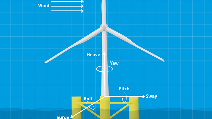
For a bottom fixed turbine, you have constraints on motions in the vertical and horizontal directions, as well as rotations, hence, the primary drivers for the design of the towers and the substructures are the thrust loads and the gravity loads. However, for a floating structure, six degrees of freedom need to be accounted for when assessing how the floating foundation behaves and responds to the external loads acting on it.

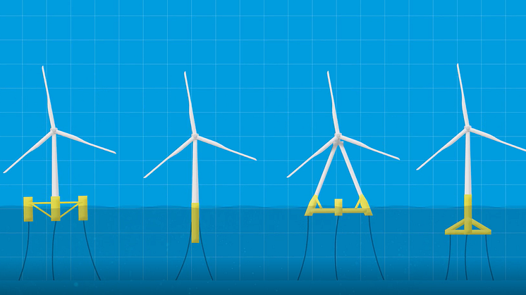
Figure 1 Types of floating wind power structures
Another round of upscaling turbine nameplates is necessary to make floating offshore wind economically profitable given several aspects, where higher interest rates, limitations in manufacture, fabrication and supply chain, and unknowns in maintenance and operations of these floating assets are considered some of the most important ones.
We have seen a convergence of spread moored semi-submersible foundation designs. The previous standard three column eccentric tower design solution has been overtaken by four-column designs with centralised towers. This convergence is the results of implementing turbines from 15 MW and upward. Moving the towers to the centre improves the dynamic response and may in fact, especially for the floating foundations with a large footprint, reduce the need for an active and complex ballast and marine systems to ensure an aligned foundation with dynamic stability. But there are consequences to all this.
Dependencies on the floating foundation, and tower design
When designing for 15MW+ turbines, significantly stronger towers are needed to withstand the additional thrust combined with the acceleration loads exerted by the floating structure. The bending and vibration due to external loads, and especially the excitation by the turbine rotor plays a significant role in design.
In this paragraph we will discuss the additional loads acting on a floating tower, and subsequently discuss some of the parameters which can be altered to compensate for these additional loads by means of:
- Stiffer towers
- Increasing trim, footprint and column diameter.
And subsequently how the main dimensional criteria’s in turn impact the dimensioning of a floating foundation. These main dimensional criteria are:
- Static tilt for rated thrust condition
- Tower bending moment for shutdown condition
- Floating stability for shutdown condition
Additional loads on floating towers
The trim angle of the floating foundation, the tilt angle of the turbine and the pitch acceleration of the integrated structure will have major impacts on the response of the whole system and force it to incline. The tower bending contributes with an additional tilt angle at the tower top, and the angular acceleration in the pitch direction adds additional stresses and bending moments on the tower wall. In operational conditions at rated thrust and when the floating foundation tilts backwards, the bending moment from gravitation increases. For a floating foundation, a pitch acceleration of maximum 1 degree/s2 corresponds to 2.6 m/s2 (0.26g) in longitudinal nacelle acceleration. Assuming a Rotor-Nacelle Assembly (RNA) of 1000 tons, this pitch acceleration translates to a 300-ton extra force acting on the RNA which needs to be taken up by the tower wall as increased bending moment. If you assume a 0.5g longitudinal nacelle acceleration, the force coming from the acceleration for the same RNA would be 500 tons. This comes in addition to the thrust force from the wind itself, which typically translates to 200 tons at the RNA for a 15 MW turbine.
Under normal production, you would assume 5-degree static pitch of the RNA to avoid tower strikes from the blades. Even this inclination of the RNA will introduce an additional gravity component force needed to be taken up by the tower wall. By using standard trigonometry, and assuming the same 1000 tons RNA, the resulting additional thrust due to the gravity component is sin(5 deg)x1000t = ~87 tons. This again introduces additional bending moment 150 meter below the RNA at the tower root.
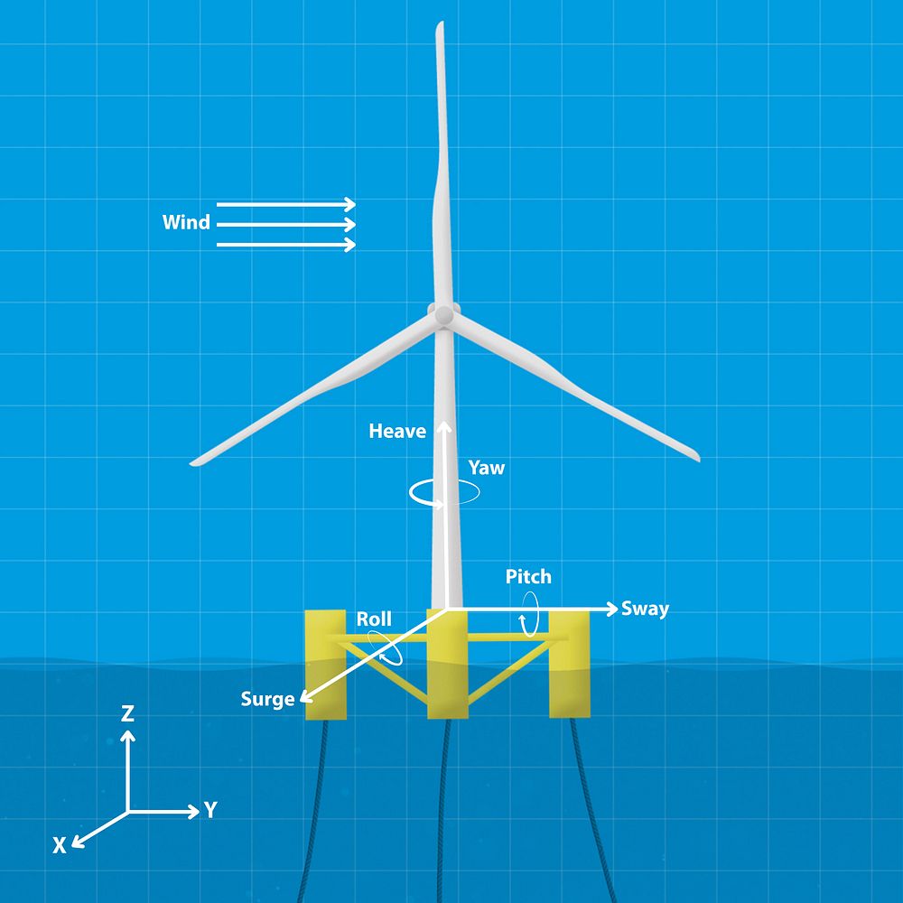
Figure 2 Forces And Motions Acting On The Floating Structure
Making the tower stiffer
When designing the tower, this additional loading is traditionally taken care of by increasing the thickness and/or the outer diameter of the tower. This will in turn provide a stiffer tower with a higher natural frequency. This means that the natural frequency of the tower will be is closer to the 3P frequency. Avoiding the 3P frequency band may in turn call for an even further increased diameter of the towers.
Introducing a stiffer tower in your design must be done with care. Firstly, there is a practical limit in the current supply chain to how large a tower diameters you can manufacture. This has to be accounted for in your supply chain philosophy.
Secondly, changing the stiffness of the tower means changing the mass of a tower. Changing the mass of the tower will affect the draft, the Centre of Buoyancy (COB) and Centre of Gravity (COG), and the natural periods of the floating structure.
Thus, implementing these changes will affect the overall performance of the floater/tower system, resulting in a full design iteration being required.
An example of various design and impact of tower angle and floating foundation trim can be seen in Figure 3 below.
Changing trim, footprint and column diameter
Increased forward trim of the floating foundation in still-water, provides more margin in operational conditions (with wind, waves, current) against the static tilt design criterion. This requires less hydrostatic stiffness (pitch) which allows for smaller floater dimensions (less column diameter or less column spacing) and generally results in more favourable motion behaviour.
However, initial forward trim has implication on tower design as well as floating stability for shutdown events. A substructure trimmed forward in initial condition will experience larger tilt angles during shutdown due to the shifted equilibrium. This generally leads to larger tower loads (due to gravity) as well as less excess restoring to avoid capsizing. So, there is a fine balance obtaining the necessary hydrostatic stiffness in relation to the trim and the static tilt of the foundation.
Hydrostatic restoring results from the second moment of waterplane area, vertical centre of gravity and centre of buoyancy. The contribution from the waterplane is usually dominating and driving the design for semi-submersibles. Thus, the criterion of static tilt, e.g. 5 degrees, in rated thrust condition is driving the dimensioning of the column spacing and column diameter.
The diameter of the columns and the column spacing (or column axis radius) are means to influence COB or COG position. Increased column spacing (resulting in increased pontoon length) increases the heave natural period of the floating system as well as structural mass. It also increases initial hydrostatic stiffness (roll, pitch) and thus reduces the static tilt angle for rated thrust conditions. With respect to floating stability, it improves initial restoring (larger GM), but it decreases stability range (columns being submerged at lower floater trim if kept at same column height).
Increased column diameter decreases the heave natural period of the floating system, increases structural mass and increases the hydrostatic stiffness (larger waterplane area) and thus reduces the static tilt angle for rated thrust conditions. In contrast to column spacing, it does not reduce the range of stability.
Thus, implementing such changes will affect the overall performance of the floater/tower system, resulting in a full design iteration being required.
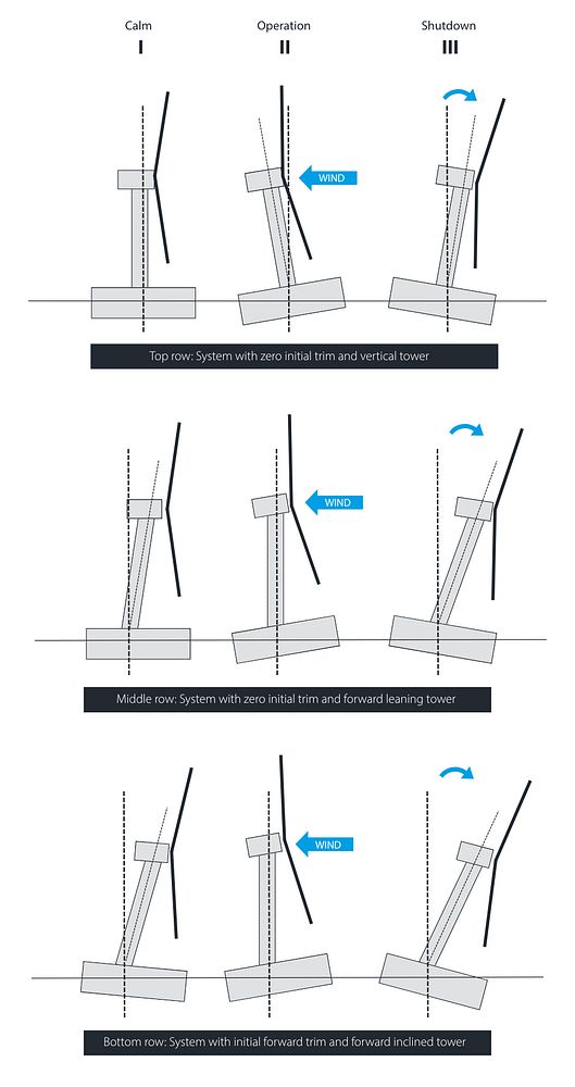
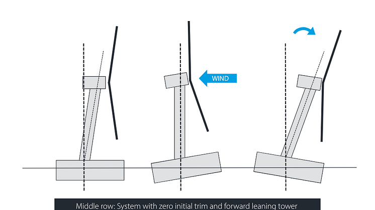
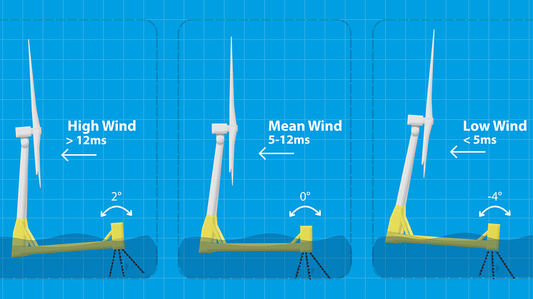
Figure 3 FOWT tower tilt for different conditions
Specific considerations for stability of forward-leaning towers
Another governing design driver for the floater dimensions is the floating stability criterion in normal sea state and for the transient, shutdown condition.
The shutdown conditions of a floating offshore wind turbine are defined as a transition between two equilibrium conditions: (I) the normal operating condition where the turbine is producing and pushed backwards, and (II) the shutdown condition where the turbine is not producing. In the transient phase between these conditions there is a phase where the system, due to inertia typically overshoots the shutdown position and tilts further forwards (see Figure 3, condition III). This transient phase can be dimensioning for the stability criterion.
To fulfil the hydrostatic stability, the height and the diameter of the forward column is increased (to increase the available restoring energy). For structures with initial forward trim (and forward inclined towers), the likelihood that the maximum tower bending is driven by shutdown conditions instead of operating condition is increased compared to systems with vertical tower and zero initial trim.
Controlling the motions
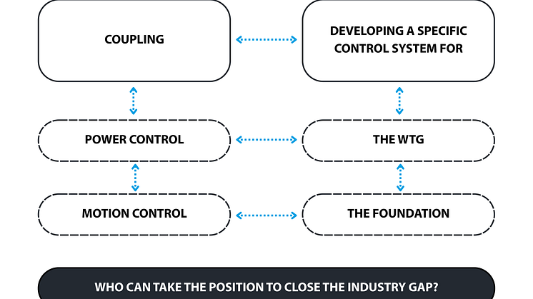
It's a prerequisite that the wind turbine operation and safety is governed by a built-in control and protection system. The behaviour described above indicates that an active control system is an enabler for a safe, robust and cost-efficient floating foundation design. Every floating foundation design needs a system that stabilises and reduces floating system motions and keep structural responses at or below the levels assumed in design. Ultimately, there is a need for a combined controller.
This combined controller needs to consider not only the characteristics of the floater itself, and the characteristics of the WTG, but there will be a need for tuning the controllers depending on the site you will be operating on and throughout the lifetime.

Where does this take us…
It is necessary to reevaluate the conventional design methods, and to adopt innovative approaches to effectively address the challenges discussed above. Here are the key reasons why:
- When moving from bottom fixed to floating offshore wind the complexity of engineering challenges significantly increases.
- Waves, wind, and currents have an impact on bottom fixed structures as well; however, the additional movement of a floating structure increases the forces acting on the WTG, the tower, the substructure, and the mooring system.
- Floating wind turbines with rating above 15 MW, calls for stronger and bigger floating foundations and towers for which new challenges arise with respect to weights and natural frequencies.
- Observing the market for fixed-moored single-tower designs it seems beneficial going for centralized towers for floating foundations design with big turbines and a stiff-stiff tower for a desired 25 year lifetime.
- Making a single tower stiff enough to elevate the frequency to make it sufficiently far away from the 3P range is not simple, and starts challenging existing supply chain.
How BRUNEL solves these challenges….
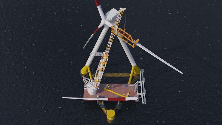
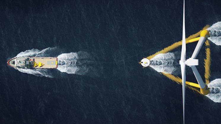
Fred. Olsen 1848 solution to this is the floating foundation BRUNEL.
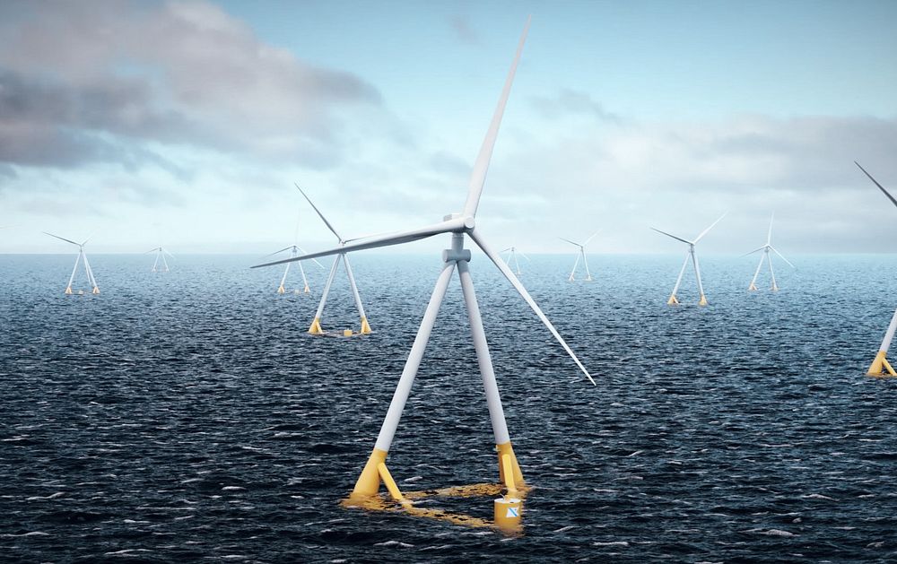
Image 1 BRUNEL Floating Foundation Design
BRUNEL’s unique approach to structural integration and design optimisation positions it as one of the solutions helping to overcome the key engineering and supply chain challenges of floating offshore wind.
The BRUNEL substructure features a very specific tower design compared to more conventional substructure concepts. It is designed as an integrated structure with dual towers, where we reduce the interface risks between WTG, tower, floating foundation and mooring system.
This provides us flexibility when it comes to ideal tower design for larger turbines. Which also results in flexibility in the supply chain, as the diameter of the towers will remain within the sweet spot of existing fabricator capacities.
The dual towers are mounted on both aft columns that connect at the top forming an A-frame. For this, both towers are inclined inwards by ~17 deg from vertical. Additionally, both towers are inclined forwards by 5 deg from vertical. The aft columns are supported by aft braces that reach diagonally upwards from the side pontoons and join the aft columns just below the tower interface.
The dual tower configuration results in an increased stiffness compared to a single tower configuration. This is much more pronounced in the transverse (side-side) direction of the towers where both towers support each other due to their inwards inclination resulting in a very stiff configuration. In longitudinal direction the increased stiffness stems from sharing of loads between both towers as well from a reduced unsupported length due to the elevated tower interface position. This results in very high eigenfrequencies for the side-side flexible bending mode of the towers.
The combination of forward inclined towers and a forward trim of the floating foundation result in reduced bending moments in operational and survival conditions. The moment resulting from the wind loads generated at the RNA and tower in these conditions result in up- righting the tower and the floating foundation. Thus, in operational conditions at rated thrust when the substructure tilts backwards by ~5 deg, the towers are directed upwards, minimizing bending moments from gravitation, see Figure 3 condition II).
Due to the forward-leaning configuration, the increased distance between the rotor blades and the tower reduces the fatigue loads and allows for maximizing the effective rotor area resulting in increased annual energy production.
However, for structures with forward inclined towers and/or initial forward trim, the likelihood that the maximum tower bending is driven by shutdown conditions instead of operating condition is greatly increased compared to systems with vertical tower and zero initial trim, so there needs to be a fine balance with the turbine controllers.
Even though there are dark skies on the horizon, floating wind one day will be important in the future energy mix. BRUNEL Floating Foundation with its dual towers may can justify the race for upscaling the turbines to obtain acceptable LCOE figures for floating offshore wind and return on investment.
In the next series of technical discussions, we will talk about the weathervaning functionality. Reach out if you want to learn more.
Author: Andreas Buvarp Aardal
Andreas Buvarp Aardal is the Lead Engineer for BRUNEL Floating Foundation and has managed the technical development over the last three years at Fred. Olsen 1848

Author: Geir Grimsrud
Geir Grimsrud is the CTO in Fred. Olsen 1848 and one of the inventors of the BRUNEL Floating Foundation.

Author: Per Arvid Holth
Per Arvid Holth is the CEO in Fred. Olsen 1848 and overall responsible for the development of BRUNEL Floating Foundation.