Blogginlägg -
Converting Dial Indicator Cold Alignment Targets with the Fixturlaser NXA
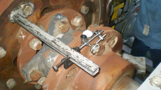
Many OEM’s, packagers, end users, and service companies use laser alignment systems, however their cold alignment targets are typically in rim & face dial indicator terms and need to be converted to laser terms.
One method to translate or convert dial indicator “speak” to laser shaft alignment “speak” is to use the free Fixturlaser Laser-Dials App available for smart devices through the Apple App Store or Google Play.
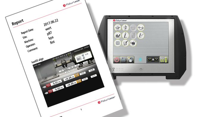
Another method is with the “Target Values Dials” Program in the Fixturlaser NXA Pro and Fixturlaser NXA Ultimate. The Target Values Program performs the dials to laser conversion then allows the aligner to save the targets then “jump” to the horizontal shaft alignment program with a touch of an on-screen icon. The Target Values Program converts both rim & face and reverse dial indicator cold target values.
From the main screen of the Fixturlaser NXA Display unit touch the “Target Values Dials” icon.

Then choose either the reverse dial or rim & face dial indicator methodology. This example will be for rim & face dials.

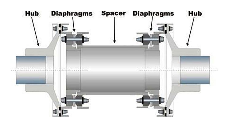
Then choose your dial indicator mounting arrangement. The left coupling hub is the compressor (stationary machine) with the engine or electric motor (movable machine) on the right. Engine driven compressor alignment typically has the dials bracket mounted to the engine flywheel with the rim indicator reading on the compressor coupling hub and the face indicator reading on the backside of the compressor coupling hub. For that arrangement the far right icon is touched.

The next screen is the rim & face mounting arrangement selected with the rim dial on the left and the face dial on the right. The user simply enters the respective rim & face dials values plus the coupling diameter and distance from the compressor coupling hub to coupling center.

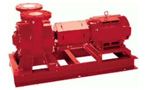
Say you are aligning a Cat 3616 engine to an Ariel JGH Compressor with an 18” diameter coupling and it’s been determined the cold alignment targets for the engine are to be – 9.0 mils (-0.009”) TIR (Total Indicator Reading) on the rim dial indicator. The thermal growth is even so the cold alignment target for the face indicator is “0”.
Enter the rim & face dial cold target values in each box with a “?” and the corresponding laser cold targets will be shown at the bottom of the screen (outlined in red). The green arrow points to the vertical and horizontal angular (face) cold target which in this case is “0”. The yellow arrow points to the vertical & horizontal offset cold target (1/2 Rim TIR) which is -4.5 mils (-0.0045”) for the vertical plane and 0 for the horizontal plane.

At this point the targets can be saved by touching the save icon ![]() or you can jump directly to the shaft alignment program by touching the coupling icon
or you can jump directly to the shaft alignment program by touching the coupling icon ![]() . The cold alignment targets will automatically be entered eliminating possible errors when manually entering targets.
. The cold alignment targets will automatically be entered eliminating possible errors when manually entering targets.
The saved cold targets file, when viewed in the NXA memory manager, also has the coupling icon shortcut to the shaft alignment program.

After touching the coupling icon ![]() to jump to the shaft alignment program a red thermometer will be displayed throughout the alignment to let the user know a cold alignment target has been entered.
to jump to the shaft alignment program a red thermometer will be displayed throughout the alignment to let the user know a cold alignment target has been entered.

You can also view the cold alignment targets when in the shaft alignment program.

So, when having to translate cold alignment targets between dial indicator “language” and laser shaft alignment “language” there are several options to do so.
Still not sure about converting dial indicator cold alignment targets to your laser targets? Give us a call we will be happy to help!


