Pressmeddelande -
Why Don’t I Input a Coupling Diameter?
We often get asked why we don’t input a coupling diameter when performing a precision shaft alignment with the ACOEM laser alignment systems. The coupling diameter (or more correctly sweep of a face dial indicator) is only required when doing a rim and face dial indicator alignment or when the user wants to know the coupling gap. The coupling gap is not the same thing as angularity.
Precision shaft alignment tolerances are typically expressed as angle and offset in vertical and horizontal directions. Most people understand offset, but angularity often causes confusion among those who are tasked with performing an alignment or verifying if an alignment is acceptable.
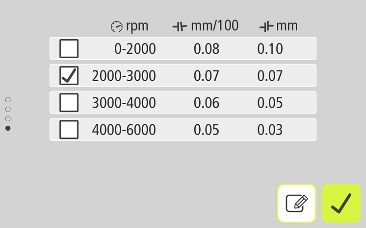
Here is an accepted tolerance table with the specification chosen for an 1800 RPM machine.
Remember 1 mil = 1 thousandth = .001″

An acceptable alignment is achieved if the angularity value is 0.7 mils/inch or less and the offset value is 4.0 mils or less in both the vertical and horizontal directions. Notice that angularity is expressed as a slope not a single number. A laser alignment system simplifies the process since it calculates everything for the user. Here is how you calculate angularity for both the rim and face and reverse dial indicator alignment methods.
1 – Rim and Face
In a rim and face reading the offset comes from ½ the value of the dial that is running around the rim of the coupling or fixture and the angularity comes from the face dial indicator. Angularity is the gap difference in both the vertical and the horizontal planes divided by the sweep of the dial (often, but not always, the coupling diameter).


If the face dial sweep is 6 inches and the gap difference is 10 mils, then the gap is 10 mils but the angularity would be 10 mils/6 inches = 1.67 mils/inch. This would be unacceptable for an 1800 rpm machine. The rise/run triangle is along the coupling or fixture face depending on the actual sweep of the dial.
2 – Reverse dial
The reverse dial measures two offsets and the slope of the line that connects them is angularity. This is the way ACOEM lasers measure. If the dials are six inches apart and the offset difference between dial 1 and dial 2 is 10 mils, then the angularity would be 10 mils/6 inches or 1.67 mils/inch. The rise-over run triangle flips 90 degrees from the rim and face and is along the shafts.


Additional Resources
Defining Angularity in Shaft Alignment
Converting Laser Alignment Data to Rim and Face using the App
Ämnen
Kategorier
Together with 150 distributors, our 800+ employees work across 26 offices, 5 manufacturing facilities and 3 R&D centres in 11 countries
Acoem links possibilities with protection.
For more information visit acoem.se